| 
| | | PicPuter 2.0 : Controlling Stepper Motors. |
PicPuter contains the logic to control 2 unipolar stepper motors.
The variables ASPEED , ASTEP , BSPEED , BSTEP are used to move the stepper motor.
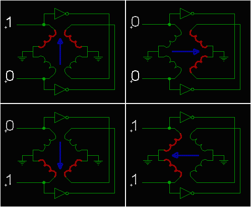
 PicPuter generates 2 signals to control each stepper motor. They appear on PortD.0 and PortD.1 for stepper A, and PortD.2 and PortD.3 for stepper B These two signals and there inverse are used as the four signals required to step the servo.
A unipolar stepper motor usually has 5 or 6 wires. Four of the wires are used to energize each of the motors four coils, while the other wires are commons. Each stepper motor seems to have a different wire setup so you may need to experiment.
Since stepper motors usually require more than 5V to operate, and a bit more current than the pic can produce, the IO must be buffered. There are quite a few chips available that will buffer the signal, you need to pay careful attention to the current that the chip can sink.
I have not done much work in this area yet. I will design a PicPuter personality board aimed tword robotics, but you are on your own for now. Here is a
link to a site that has a typical low power solution.
The CONFIGURATOR ROBOT_PORT bit (bit 2) must be set. (SETCON2)
If TRISD has been modified for its default value, must be reset to outputs.
|


 PicPuter generates 2 signals to control each stepper motor. They appear on PortD.0 and PortD.1 for stepper A, and PortD.2 and PortD.3 for stepper B These two signals and there inverse are used as the four signals required to step the servo.